
Most local area networks are built with relatively inexpensive hardware such as Ethernet cables, network adapters, and hubs. Wireless LAN and other more advanced LAN hardware options also exist.
Specialized operating system software may be used to configure a local area network. For example, most flavors of Microsoft Windows provide a software package called Internet Connection Sharing (ICS) that supports controlled access to LAN resources.
The term LAN party refers to a multiplayer gaming event where participants bring their own computers and build a temporary LAN.
More about Lan ----
Introduction to LAN Protocols
This chapter introduces the various media-access methods, transmission methods, topologies, and devices used in a local-area network (LAN). Topics addressed focus on the methods and devices used in Ethernet/IEEE 802.3, Token Ring/IEEE 802.5, and Fiber Distributed Data Interface (FDDI). Subsequent chapters in Part II, "LAN Protocols," address specific protocols in more detail. Figure 2-1 illustrates the basic layout of these three implementations.
Figure 2-1 Three LAN Implementations Are Used Most Commonly

What Is a LAN?
A LAN is a high-speed data network that covers a relatively small geographic area. It typically connects workstations, personal computers, printers, servers, and other devices. LANs offer computer users many advantages, including shared access to devices and applications, file exchange between connected users, and communication between users via electronic mail and other applications.
LAN Protocols and the OSI Reference Model
LAN protocols function at the lowest two layers of the OSI reference model, as discussed in Chapter 1, "Internetworking Basics," between the physical layer and the data link layer. Figure 2-2 illustrates how several popular LAN protocols map to the OSI reference model.
Figure 2-2 Popular LAN Protocols Mapped to the OSI Reference Model

LAN Media-Access Methods
Media contention occurs when two or more network devices have data to send at the same time. Because multiple devices cannot talk on the network simultaneously, some type of method must be used to allow one device access to the network media at a time. This is done in two main ways: carrier sense multiple access collision detect (CSMA/CD) and token passing.
In networks using CSMA/CD technology such as Ethernet, network devices contend for the network media. When a device has data to send, it first listens to see if any other device is currently using the network. If not, it starts sending its data. After finishing its transmission, it listens again to see if a collision occurred. A collision occurs when two devices send data simultaneously. When a collision happens, each device waits a random length of time before resending its data. In most cases, a collision will not occur again between the two devices. Because of this type of network contention, the busier a network becomes, the more collisions occur. This is why performance of Ethernet degrades rapidly as the number of devices on a single network increases.
In token-passing networks such as Token Ring and FDDI, a special network frame called a token is passed around the network from device to device. When a device has data to send, it must wait until it has the token and then sends its data. When the data transmission is complete, the token is released so that other devices may use the network media. The main advantage of token-passing networks is that they are deterministic. In other words, it is easy to calculate the maximum time that will pass before a device has the opportunity to send data. This explains the popularity of token-passing networks in some real-time environments such as factories, where machinery must be capable of communicating at a determinable interval.
For CSMA/CD networks, switches segment the network into multiple collision domains. This reduces the number of devices per network segment that must contend for the media. By creating smaller collision domains, the performance of a network can be increased significantly without requiring addressing changes.
Normally CSMA/CD networks are half-duplex, meaning that while a device sends information, it cannot receive at the time. While that device is talking, it is incapable of also listening for other traffic. This is much like a walkie-talkie. When one person wants to talk, he presses the transmit button and begins speaking. While he is talking, no one else on the same frequency can talk. When the sending person is finished, he releases the transmit button and the frequency is available to others.
When switches are introduced, full-duplex operation is possible. Full-duplex works much like a telephone—you can listen as well as talk at the same time. When a network device is attached directly to the port of a network switch, the two devices may be capable of operating in full-duplex mode. In full-duplex mode, performance can be increased, but
not quite as much as some like to claim. A 100-Mbps Ethernet segment is capable of transmitting 200 Mbps of data, but only 100 Mbps can travel in one direction at a time. Because most data connections are asymmetric (with more data traveling in one direction than the other), the gain is not as great as many claim. However, full-duplex operation does increase the throughput of most applications because the network media is no longer shared. Two devices on a full-duplex connection can send data as soon as it is ready.
Token-passing networks such as Token Ring can also benefit from network switches. In large networks, the delay between turns to transmit may be significant because the token is passed around the network.
LAN Transmission Methods
LAN data transmissions fall into three classifications: unicast, multicast, and broadcast.
In each type of transmission, a single packet is sent to one or more nodes.
In a unicast transmission, a single packet is sent from the source to a destination on a network. First, the source node addresses the packet by using the address of the destination node. The package is then sent onto the network, and finally, the network passes the packet to its destination.
A multicast transmission consists of a single data packet that is copied and sent to a specific subset of nodes on the network. First, the source node addresses the packet by using a multicast address. The packet is then sent into the network, which makes copies of the packet and sends a copy to each node that is part of the multicast address.
A broadcast transmission consists of a single data packet that is copied and sent to all nodes on the network. In these types of transmissions, the source node addresses the packet by using the broadcast address. The packet is then sent on to the network, which makes copies of the packet and sends a copy to every node on the network.
LAN Topologies
LAN topologies define the manner in which network devices are organized. Four common LAN topologies exist: bus, ring, star, and tree. These topologies are logical architectures, but the actual devices need not be physically organized in these configurations. Logical bus and ring topologies, for example, are commonly organized physically as a star. A bus topology is a linear LAN architecture in which transmissions from network stations propagate the length of the medium and are received by all other stations. Of the three
most widely used LAN implementations, Ethernet/IEEE 802.3 networks—including 100BaseT—implement a bus topology, which is illustrated in Figure 2-3.
Figure 2-3 Some Networks Implement a Local Bus Topology

A ring topology is a LAN architecture that consists of a series of devices connected to one another by unidirectional transmission links to form a single closed loop. Both Token Ring/IEEE 802.5 and FDDI networks implement a ring topology. Figure 2-4 depicts a logical ring topology.
Figure 2-4 Some Networks Implement a Logical Ring Topology

A star topology is a LAN architecture in which the endpoints on a network are connected to a common central hub, or switch, by dedicated links. Logical bus and ring topologies are often implemented physically in a star topology, which is illustrated in Figure 2-5.
A tree topology is a LAN architecture that is identical to the bus topology, except that branches with multiple nodes are possible in this case. Figure 2-5 illustrates a logical tree topology.
Figure 2-5 A Logical Tree Topology Can Contain Multiple Nodes

LAN Devices
Devices commonly used in LANs include repeaters, hubs, LAN extenders, bridges, LAN switches, and routers.

Note ![]() Repeaters, hubs, and LAN extenders are discussed briefly in this section. The function and operation of bridges, switches, and routers are discussed generally in Chapter 4, "Bridging and Switching Basics," and Chapter 5, "Routing Basics."
Repeaters, hubs, and LAN extenders are discussed briefly in this section. The function and operation of bridges, switches, and routers are discussed generally in Chapter 4, "Bridging and Switching Basics," and Chapter 5, "Routing Basics."
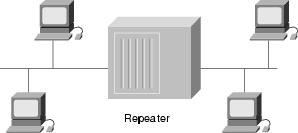
A repeater is a physical layer device used to interconnect the media segments of an extended network. A repeater essentially enables a series of cable segments to be treated as a single cable. Repeaters receive signals from one network segment and amplify, retime, and retransmit those signals to another network segment. These actions prevent signal deterioration caused by long cable lengths and large numbers of connected devices. Repeaters are incapable of performing complex filtering and other traffic processing. In addition, all electrical signals, including electrical disturbances and other errors, are repeated and amplified. The total number of repeaters and network segments that can be connected is limited due to timing and other issues. Figure 2-6 illustrates a repeater connecting two network segments.
Figure 2-6 A Repeater Connects Two Network Segments
A hub is a physical layer device that connects multiple user stations, each via a dedicated cable. Electrical interconnections are established inside the hub. Hubs are used to create a physical star network while maintaining the logical bus or ring configuration of the LAN. In some respects, a hub functions as a multiport repeater.
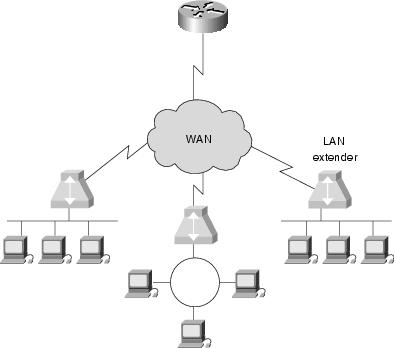
A LAN extender is a remote-access multilayer switch that connects to a host router. LAN extenders forward traffic from all the standard network layer protocols (such as IP, IPX, and AppleTalk) and filter traffic based on the MAC address or network layer protocol type. LAN extenders scale well because the host router filters out unwanted broadcasts and multicasts. However, LAN extenders are not capable of segmenting traffic or creating security firewalls. Figure 2-7 illustrates multiple LAN extenders connected to the host router through a WAN.
Figure 2-7 Multiple LAN Extenders Can Connect to the Host Router Through a WAN
Review Questions
Q—Describe the type of media access used by Ethernet.
A—Ethernet uses carrier sense multiple access collision detect (CSMA/CD). Each network station listens before and after transmitting data. If a collision is detected, both stations wait a random time before trying to resend.
Q—Describe the type of media access used by Token Ring.
A—Token Ring passes a special type of packet called a token around the network. If a network device has data to send, it must wait until it has the token to send it. After the data has been sent, the token is released back on the network.
Q—Describe unicast, multicast, and broadcast transmissions.
A—A unicast is a transmission from one source to one destination. A multicast is a transmission from one source to many stations that register to receive the traffic. A broadcast is a transmission from one source to every station on the local network segment.
For More Information
Cisco's web site (www.cisco.com) is a wonderful source for more information about these topics. The Documentation section includes in-depth discussions on many of the topics covered in this chapter.
Teare, Diane. Designing Cisco Networks. Indianapolis: Cisco Press, July 1999.

1 responce(s):
Basic introduction. Hopefully you would publish network designing diagram. Thanks.
Post a Comment