Hello Guest! Welcome to ep6network, Get all components from Basic Networking.
Something you might want to know about us.
Don't be hesitated to contact us if you have something to say.

IP,IPv6 Routing Protocols, Internet protocols version six, IPv6

| 2 responce(s) | Sunday, August 9, 2009
|

Source :
Deploying IPv6 Networks
By Ciprian Popoviciu, Eric Levy-Abegnoli, Patrick Grossetete
...............................................
Publisher: Cisco Press
Pub Date: February 10, 2006
IPv6 Packet Format
IPv6 Routing Protocols

Numerous IPv4 routing protocols (RPs) are available for finding routes between networks, and almost every one of them has an IPv6 correspondent or extension: Routing Information Protocol next-generation (RIPng), Open Shortest Path First version 3 (OSPFv3), Intermediate System-to-Intermediate System (IS-IS), Enhanced Interior Gateway Routing Protocol (EIGRP), and Border Gateway Protocol (BGP). So far, IPv6 has brought few innovations to the IP routing paradigm. There are still interior gateway protocols (IGPs) and exterior gateway protocols (EGPs), distance vectorbased and link-state-based routing protocol algorithms, and so on.

The concept of the autonomous system, defined as a set of networks controlled by a common administrative entity, remains unchanged with the introduction of IPv6 RPs. The same autonomous system (and autonomous system number [ASN]) will route both IPv4 and IPv6. IPv6 IGPs, used to exchange routes within the autonomous system, are namely RIPng, OSPFv3, IS-IS for IPv6, and EIGRP for IPv6. Only BGP4 is available to exchange IPv6 routes between autonomous systems. Multiprotocol extensions provide support in BGP4 for IPv6 routing.

The requirements for IGPs and EGPs are quite different, in terms of routing table size, number of supported routers, convergence time, security, routing policy, and so forth. For that reason, they use different algorithms and mechanisms, which also affect the type of information they exchange and store. IGPs use distance vector and link state, whereas BGP uses the path vector RP algorithm. The following table represents RP taxonomy, and highlights their IPv6 correspondent. For more details on how to choose the RP, refer to Top-Down Network Design, Second Edition, by Priscilla Oppenheimer.

Table 4-1. Taxonomy of Routing Protocols

Deployment Domain

Algorithm

RP

Scalability

Convergence Time

Metric

IPv6 Version

Interior gateway protocol (IGP)

Distance vector

RIP

15 hops

Slow

Hop count

RIPng


EIGRP

1000s routers

Quick (via DUAL algorithm)

Bandwidth, delay, reliability, load

EIGRP for IPv6


Link state

OSPF

1000s routers (100s/area)

Quick (via LSAs and HELLO)

Cost (function of bandwidth on Cisco routers)

OSPFv3


IS-IS

1000s routers (100s/area)

Quick (via LSPs)

Configured host, delay, expense

IS-IS for IPv6

Exterior gateway protocol (EGP)

Distance vector

EGP


Integer <=255


Path vector

BGP AF=IPv4

1000s routers

Slow (via UPDATE)

Function of path attributes and other configurable factors

BGP AF=IPv6


The rest of this section briefly reviews existing unicast RP technologies. The next section reviews each of the available IPv6 RPs and provides configuration examples. Then the last two sections cover the topic of multihoming and deployment aspects, respectively.


IP Mobility, IP, IPv6, IP version 6, Internet protocol

| 1 responce(s) |
|

Source :
Deploying IPv6 Networks
By Ciprian Popoviciu, Eric Levy-Abegnoli, Patrick Grossetete
...............................................
Publisher: Cisco Press
Pub Date: February 10, 2006

IP Mobility


The Internet has become so pervasive that no matter where you are, you can plug your computer into a wall, or attach to a wireless LAN, and, after a while, you will be able to communicate. Is not this mobility? Well, not quite.

That type of "mobility" is achieved by getting a new IP address within the network of attachment and losing all sessions bound to the previous IP address. This might be acceptable for corporate users moving from work to home, but can be much more cumbersome for road warriors, and it can be a showstopper for IP telephony.

Mobile IP provides a network layer for hosts that enables them to maintain the same IP address no matter where they are in the Internet, and keep receiving traffic as they move.

"Advanced ServicesIPv6 Mobility," MIPv6 is compared to MIPv4. Even though MIPv4 is a mature and deployable technology, it faces limitations because of the nature of IPv4. At the same time, IPv6 mobility is considered as one potential enabler for IPv6. The number of IP-enabled devices and the need for any-to-any communications among them is driving requirements that IPv4 cannot easily satisfy, and it is opening opportunities for IPv6. By integrating functionalities designed for Mobile IPv4 into standard IPv6 protocols, and by leveraging existing IPv6 capabilities, MIPv6 has built up a MIP model that is much more compelling than its IPv4 counterpart.

It must be noted that enhancements to mobility are largely taking place in IPv6 related working groups, even though a fraction gets retrofitted into the IPv4 standards. Although MIPv6 has benefited greatly from its MIPv4 parent, it is now the driver of the evolution of IP mobility, and it is widely expected to be a foremost steering force for IPv6 deployments.

In terms of deployment, it must be considered that IP mobility enables new flows, which impact the wireless infrastructure: Telephony over IP demands a higher level of coverage, latency, and QoS enforcement, whereas peer to peer imposes always-on reachability and multimedia capabilities.

The application of the MIP and NEtwork MObility (NEMO) standards is not limited to hosts and routers that actually roam around the Internet as a usual behavior. Sales of consumer routers are plummeting. At the moment, they are related to IPv4 NAT operations. With IPv6, it can be expected that people will deploy unmanaged yet globally addressable networks at home. NEMO support by the home gateways would enable a service provider to deploy preprovisioned devices, and could save hundreds of thousands of network-renumbering operations per year as customers move from one home to the next.

At the core, MIP builds dynamic tunnels, and NEMO exchanges routes over those tunnels. In a way, this is a revamping of the traditional model of the core where BGP routers exchange the bulk of the Internet routes over peering tunnels. But whereas the model of the Internet is designed for fixed, aggregated routes that are locally injected and slowly distributed throughout its fabric, MIP and NEMO techniques enable a new model where routes are projected where and when they are needed, on-demand; this opens to a new level of hierarchy for the fine-grained mobile routes, and a new order of scalability for the Internet.

But the Internet of today is not fully ready for IP mobility. Even if IPv6 can exist over an IPv4 fabric as a transitional method, a significant number of improvements must be made to cope with the latency of the protocol and enable multimedia interactive applications such as voice calls and video.


Data Cabling Rules,Reliable Cabling, Poor Cabling Cost

| 6 responce(s) | Sunday, August 2, 2009
|

The Golden Rules of Data Cabling,The Importance of Reliable Cabling,The Legacy of Proprietary Cabling Systems, Cabling and the Need for Speed, Cable Design , Data Communications 101, Speed Bumps: What Slows Down Your Data, The Future of Cabling Performance. Learn how to Cabling, Know that better than the best.


Source: Cabling:The Complete Guide to Network Wiring (Third Edition)
Author : David Barnett, David Groth, Jim McBee.

“Data cabling! It’s just wire. What is there to plan?” the newly promoted programmer turned MIS-director commented to Jim. The MIS director had been contracted to help the company move its 750-node network to a new location. During the initial conversation, the director had a couple of other “insights”:
He said that the walls were not even up in the new location, so it was too early to be talking about data cabling.
To save money, he wanted to pull the old Category 3 cabling and move it to the new location. (“We can run 100Base-TX on the old cable.”)
He said not to worry about the voice cabling and the cabling for the photocopier tracking system; someone else would coordinate that. Jim shouldn’t have been too surprised by the ridiculous nature of these comments. Too few people understand the importance of a reliable, standards-based, flexible cabling system. Fewer still understand the challenges of building a high-speed network. Some of the technical problems associated with building a cabling system to support a high-speed network are comprehended only by electrical engineers. And many believe that a separate type of cable should be in the wall for each application (PCs, printers, terminals, copiers, etc.). Data cabling has come a long way in the past 20 years. This chapter discusses some of the basics of data cabling, including topics such as:

●The golden rules of data cabling
●The importance of reliable cabling
●The legacy of proprietary cabling systems
●The increasing demands on data cabling to support higher speeds
●Cable design and materials used to make cables
●Types of communications media
●Limitations that cabling imposes on higher-speed communications
●The future of cabling performance

You are probably thinking right now that all you really want to know is how to install cable to support a few 10Base-T workstations. Words and phrases such as attenuation,crosstalk,twisted pair,modular connectors, and multi-mode optical-fiber cable may be completely foreign to you. Just as the world of PC LAN's and WANs has its own industry buzzwords, so does the cabling business. In fact, you may hear such an endless stream of buzzwords and foreign terminology that you’ll wish you had majored in electrical engineering in college. But it’s not really that mysterious and, armed with the background and information we’ll provide, you’ll soon be using cable speak like a cabling professional.

The Golden Rules of Data Cabling

Listing our own golden rules of data cabling is a great way to start this chapter and the book. If your cabling is not designed and installed properly, you will have problems that you can’t even imagine. From our experience, we’ve become cabling evangelists, spreading the good news of proper cabling. What follows is our list of rules to consider when planning structuredcabling systems:

●Networks never get smaller or less complicated.
●Build one cabling system that will accommodate voice and data.
●Always install more cabling than you currently require. Those extra outlets will come in
handy someday.
●Use structured-cabling standards when building a new cabling system. Avoid anything
proprietary!
●Quality counts! Use high-quality cabling and cabling components. Cabling is the foundation of your network; if the cabling fails, nothing else will matter. For a given grade or category of cabling, you’ll see a range of pricing, but the highest prices don’t necessarily mean the highest quality. Buy based on the manufacturer’s reputation and proven performance, not the price.
●Don’t scrimp on installation costs. Even quality components and cable must be installed correctly; poor workmanship has trashed more than one cabling installation.
●Plan for higher speed technologies than are commonly available today. Just because 1000Base-T Ethernet seems unnecessary today does not mean it won’t be a requirement in five years.
●Documentation, although dull, is a necessary evil that should be taken care of while you’re setting up the cabling system. If you wait, more pressing concerns may cause you to ignore it.

The Importance of Reliable Cabling

We cannot stress enough the importance of reliable cabling. Two recent studies vindicated our evangelical approach to data cabling. The studies showed:

●Data cabling typically accounts for less than 10 percent of the total cost of the network infrastructure.
●The life span of the typical cabling system is upwards of 16 years. Cabling is likely the second most long-lived asset you have (the first being the shell of the building).
●Nearly 70 percent of all network-related problems are due to poor cabling techniques and cable-component problems.

Of course, these were facts that we already knew from our own experiences. We have spent countless hours troubleshooting cabling systems that were nonstandard, badly designed, poorly documented, and shoddily installed. We have seen many dollars wasted on the installation of additional cabling and cabling infrastructure support that should have been part of the original installation. Regardless of how you look at it, cabling is the foundation of your network. It must be reliable!

The Cost of Poor Cabling

The costs that result from poorly planned and poorly implemented cabling systems can be staggering. One company that had recently moved into a new office space used the existing cabling, which was supposed to be Category 5 cable. Almost immediately, 100Mbps Ethernet network users reported intermittent problems.

These problems included exceptionally slow access times when reading e–mail, saving documents, and using the sales database. Other users reported that applications running under Windows 98 and Windows NT were locking up, which often caused them to have to reboot their PC. After many months of network annoyances, the company finally had the cable runs tested. Many cables did not even meet the minimum requirements of a Category 5 installation, and other cabling runs were installed and terminated poorly.


Network Fundamental and its Components

| 1 responce(s) | Tuesday, July 28, 2009
|

Source : Microsoft Encyclopedia of Networking Second edition

What Is Networking?

In the simplest sense, networking means connecting computers so that they can share files, printers, applications, and other computer-related resources. The advantages of networking computers are fairly obvious:
● Users can save their important files and documents on a file server. This is more secure than storing them on workstations because a file server can be backed up in a single operation.
● Users can share a network printer, which costs much less than having a locally attached printer for each user’s computer.
● Users can share groupware applications running on application servers, which enables users to share documents, send messages, and collaborate directly.
● The job of administering and securing a company’s computer resources is simplified since they are concentrated on a few centralized servers. The above definition of networking focuses on the basic goals of networking computers together: increased manageability, security, cost-effectiveness, and efficiency over non-networked systems. However, we could also focus our discussion on the different types of networks, including
● Personal area networks (PANs), once the stuff of science fiction but rapidly becoming a reality as the mobile knowledge workers of today carry around an array of cell phones, Personal Digital Assistants (PDAs), pagers, and other small devices
● Local area networks (LANs), which can range from a few desktop workstations in a Small Office/Home Office (SOHO) to several thousand workstations and dozens of servers deployed throughout dozens of buildings on a university campus or in an industrial park
● Metropolitan area networks (MANs), which span an urban area and are generally run by telcos and other service providers to provide companies with high-speed connectivity between branch offices and with the Internet
● Wide area networks (WANs), which might take the form of a company’s head office linked to a few branch offices or an enterprise spanning several continents with hundreds of offices and subsidiaries
● The Internet, the world’s largest network and the “network of networks” On the other hand, we could also focus on the different networking architectures in which these various types of networks can be implemented, including
● Peer-to-peer networking, which might be implemented in a workgroup consisting of computers running Microsoft Windows 98 or Windows 2000 Professional
● Server-based networking, which might be based on the domain model of Windows NT, the domain trees and forests of Active Directory directory service in Windows 2000, or another architecture such as Novell Directory Services (NDS) for Novell NetWare
● Terminal-based networking, which might be the traditional host-based mainframe environment; the UNIX X Windows environment; the terminal services of Windows NT Server 4 Enterprise Edition; Windows 2000 Advanced Server; or Citrix MetaFrame Or we could look at the various networking technologies used to implement these architectures, including
● LAN technologies such as Ethernet, Token Ring, Fiber Distributed Data Interface (FDDI), Fast
Ethernet, Gigabit Ethernet (GbE), and the emerging 10G Ethernet (10GbE)
● WAN technologies such as Integrated Services Digital Network (ISDN), T-carrier leased lines, X.25, frame relay, Asynchronous Transfer Mode (ATM), Synchronous Optical Network (SONET), Digital Subscriber Line (DSL), and metropolitan Ethernet
● Wireless communication technologies such as the wireless LAN (WAN) standards 802.11a and
802.11b, and the consumer wireless technologies HomeRF and Bluetooth
● Cellular communication systems such as Time Division Multiple Access (TDMA), Code Division
Multiple Access (CDMA), Global System for Mobile Communications (GSM), and the emerging
3G cellular communication standards In addition, we could consider the hardware used to
implement these different networking technologies, including
● LAN devices such as repeaters, concentrators, bridges, hubs, Ethernet switches, and routers
● WAN devices such as modems, ISDN terminal adapters, Channel Service Units (CSUs), Data Service Units (DSUs), packet assembler/disassemblers (PADs), frame relay access devices (FRADs), multiplexers (MUXes), and inverse multiplexers (IMUXes)
● Equipment for organizing, protecting, and troubleshooting LAN and WAN hardware, such as racks, cabinets, surge protectors, line conditioners, uninterruptible power supplies (UPSs), KVM switches, and cable testers
● Cabling technologies such as coaxial cabling, twinax cabling, twisted-pair cabling, fiber-optic cabling, and associated equipment such as connectors, patch panels, wall plates, and splitters
● Unguided media technologies such as infrared communication, wireless cellular networking, and satellite networking, along with their associated hardware
● Data storage technologies such as redundant array of independent disks (RAID), network-attached storage (NAS), and storage area networks (SANs) along with their associated hardware, plus various enabling technologies, including Small Computer System Interface (SCSI) and Fibre Channel Or we could talk about various technologies that enhance the reliability, scalability, security, and manageability of computer networks, including
● Technologies for implementing network security, including firewalls, proxy servers, and virtual private networking (VPN), and such devices as smart cards and firewall appliances
● Technologies for increasing availability and reliability of access to network resources, such as clustering, caching, load balancing, Layer 7 switching, and terminal services
● Network management technologies such as Simple Network Management Protocol (SNMP), Remote Network Monitoring (RMON), Web-Based Enterprise Management (WBEM), Common Information Model (CIM), and Windows Management Instrumentation (WMI) Returning to a more general level, networking can also be thought of as the various standards that underlie the
different networking technologies and hardware mentioned above, including
● The Open Systems Interconnection (OSI) networking model from the International Organization for Standardization (ISO)
● The G-series, H-series, I-series, T-series, V-series, and X-series standards from the International Telecommunication Union (ITU)
● Project 802 of the Institute of Electrical and Electronics Engineers (IEEE)
● The Requests for Comment (RFC) series from the Internet Engineering Task Force (IETF)
● Various standards developed by the World Wide Web Consortium (W3C), the Frame Relay Forum, the ATM Forum, the Gigabit Ethernet Alliance, and other standards organizations Networking protocols deserve special attention in any definition of the word networking. These protocols include:
● LAN protocols such as NetBEUI, Internetwork Packet Exchange/Sequenced Packet Exchange
(IPX/SPX), Transmission Control Protocol/Internet Protocol (TCP/IP), and AppleTalk
● WAN protocols such as Serial Line Internet Protocol (SLIP), Point-to-Point Protocol (PPP), Point-to- Point Tunneling Protocol (PPTP), and Layer 2 Tunneling
Protocol (L2TP)
● Protocols developed within mainframe computing environments, such as Systems Network Architecture (SNA), Advanced Program-to-Program Communications (APPC), Synchronous Data Link Control (SDLC), and High-level Data Link Control (HDLC)
● Routing protocols such as the Routing Information Protocol (RIP), Interior Gateway Routing Protocol (IGRP), Open Shortest Path First (OSPF) Protocol, and Border Gateway Protocol (BGP)
● Internet protocols such as the Hypertext Transfer Protocol (HTTP), File Transfer Protocol (FTP), Network News Transfer Protocol (NNTP), and the Domain Name System (DNS)
● Electronic messaging protocols such as X.400, Simple Mail Transfer Protocol (SMTP), Post Office Protocol version 3 (POP3), and Internet Mail Access Protocol version 4 (IMAPv4)
● Directory protocols such as X.500’s Directory Access Protocol (DAP) and the Lightweight Directory Access Protocol (LDAP)
● Security protocols such as Password Authentication Protocol (PAP), Challenge Handshake Authentication Protocol (CHAP), Windows NT LAN Manager (NTLM) Authentication, Kerberos, IP Security Protocol (IPsec), Secure Sockets Layer (SSL), and public key cryptography standards and protocols
● Serial interface standards such as RS-232, RS-422/ 423, RS-485, V.35, and X.21
We could dig still deeper and discuss the fundamental engineering concepts that underlie the various networking technologies and services previously discussed, including
● Impedance, attenuation, shielding, near-end crosstalk (NEXT), and other characteristics of cabling and other transmission systems
● Signals and how they can be multiplexed using time-division, frequency-division, statistical, and other multiplexing techniques
● Transmission parameters including bandwidth, throughput, latency, jabber, jitter, backbone, handshaking, hop, dead spots, dark fiber, and late collisions
● Balanced vs. unbalanced signals, baseband vs. broadband transmission, data communications equipment (DCE) vs. data terminal equipment (DTE), circuit switching vs. packet switching, connection-oriented vs. connectionless communication, unicast vs. multicast and broadcast, pointto- point vs. multipoint links, direct sequencing vs. frequency hopping methods, and switched virtual circuit (SVC) vs. permanent virtual circuit (PVC) We could also talk about the different types of providers of networking services, including
● Internet service providers (ISPs), application service providers (ASPs), and integrated communications providers (ICPs)
● Telcos or local exchange carriers (LECs), including both Regional Bell Operating Companies (RBOCs) and competitive local exchange carriers (CLECs), that offer such popular broadband services as Asymmetric Digital Subscriber Line (ADSL) and High-bit-level Digital Subscriber Line (HDSL) through their central office (CO) and local loop connection
● Inter-exchange carriers (IXCs) that provide popular WAN services such as dedicated leased lines and frame relay for the enterprise (large companies)
● Local loop alternatives including cable modems, fixed wireless, and satellite networking companies We could also list the various software technologies vendors have developed that make computer networking both useful and possible, including
● Network operating systems such as Windows, Novell NetWare, UNIX, and Linux
● Specialized operating systems such as Cisco Systems’ Internetwork Operating System (IOS), which runs on Cisco routers, and the variant of IOS used on Cisco’s Catalyst line of Ethernet switches
● Directory systems such as Microsoft Corporation’s domain-based Active Directory, Novell Directory Services (NDS), and various implementations of X.500 and LDAP directory systems
● File systems such as NTFS file system (NTFS) on Windows platforms and distributed file systems such as the Network File System (NFS) developed by Sun Microsystems for the UNIX platform
● Programming languages and architectures for developing distributed computing applications, such as the C/C++ and Java languages, Microsoft’s ActiveX and Sun’s Jini technologies, component technologies such as Distributed Component Object Model (DCOM) and COM+, inter process communication (IPC) technologies such as Remote Procedure Calls (RPCs) and named pipes, and Internet standards such as the popular Hypertext Markup Language (HTML) and the Extensible Markup Language (XML) family of standards
● Tools for integrating networking technologies in heterogeneous environments, such as Gateway Services for NetWare (GSNW), Services for Macintosh, Services for UNIX on the Windows 2000 platforms, and Microsoft Host Integration Server, all of which provide connectivity with mainframe systems On an even deeper level, we could focus on the various administration tools for managing networking hardware, platforms, services and protocols, including
● The Microsoft Management Console (MMC) and its various snap-ins in the Windows 2000 and
Windows .NET Server platforms
● The various ways routers and network appliances can be administered using Telnet, terminal programs, and the universal Web browser interface
● Popular TCP/IP command-line utilities such as arp, ping, ipconfig, traceroute, netstat, nbtstat, finger, and nslookup
● Platform-specific command-line utilities such as various Windows commands used for automating common administration tasks
● Cross-platform scripting languages that can be used for system and network administration, including JavaScript, VBScript, and Perl We could also look at various enterprise applications widely used in networked environments, including
● Enterprise Resource Planning (ERP) and Customer Relationship Management (CRM) platforms
● Enterprise Information Portal (EIP) and Enterprise Knowledge Portal (EKP) platforms
● The Microsoft .NET Enterprise Server family of applications that includes Microsoft Application Center Server, BizTalk Server, Commerce Server,Exchange Server, Host Integration Server, Internet Security and Acceleration Server, Mobile Information Server, and SQL Server I think that you can see by now that we could go on and on, slowly unpeeling our answer to the question “What is networking?” like the many layers of an onion. And it is pretty obvious by now that there is more to networking than just hubs and cables! In fact, the field of computer networking today is almost overwhelming in its breadth and complexity, and one could spend a lifetime studying only one small aspect of the subject. This has not always been the case. Let’s take a look now at how the field of computer networking has reached the amazing point where it is today.


How to Setup a LAN

| 1 responce(s) | Thursday, June 11, 2009
|

Check how to set a lan between two or more computers, full tricks to lan set up information, Configuration the LAN was not so much easy before that so keep continue reading to set a lan


SETTING UP YOUR OWN LAN

LAN Overview

This chapter shows how to set up a local network in your home or office (if you already have a functioning network, feel free to skip to the next chapter). In the next few pages, we’ll take a look at:


· The basics of network hardware

· Basic hardware requirements for your local network

· Installing the hardware and setting up a local peer-to-peer network

· Inspecting and changing network settings

A. NETWORK HARDWARE BASICS

Cables. We recommend Category 5 cables for new users. Officially called Ethernet 10/100BaseT,
they’re the most common type of network cable and provide a good upgrade path should you need it. Cat 5 allows either 10- or 100-megabyte communication. These terms have simple meanings, so don’t let them put you off:

· The “10” or “100” in 10/100BaseT refers to network connection speed—i.e., 10 Megabits or 100 Megabits per second. Most networks actually top out at less, though most users would never know.

· The “T” in BaseT refers to the wire type, twisted-pair, which consists of pairs of thin wires twisted around each other. It also refers to the connector, commonly called an RJ-45, which resembles a bigger and wider telephone connector.

· “Base” means that the cable is used for baseband (i.e., simple, single frequency) rather than broadband (multiplex or analog) networks. Cables can be purchased in different lengths and often different colors. They come with a male RJ-45 plug at each end. Cards and hubs have female RJ-45 jacks. Network Cards. A wide variety of network cards—officially called Network Interface Cards and nicknamed NICs—is available. Most do at least an adequate job. If you’re a novice networker, the primary things to look for are:

· Connection Jack. Be sure the NIC’s jack matches the type of cable you’re using. If you’re using 10BaseT cable, for instance, the NIC you buy should have an RJ-45 compatible connector.

· Plug and Play compatibility. This feature allows Windows 95/98 to automatically configure the card, saving you a lot of time in the process.

· Interrupt Addresses. Interrupts on any machine are at a premium, so you’ll want to determine
which ones the NIC has available. Generally, the more you pay, the more latitude you’ll have. ISA-bus cards are usually fast enough for a 10BaseT network; if you’re running 100BaseT you’ll
probably want to go with PCI-bus card for speed. If you’ve only got one interrupt left and must add two cards, use two PCI-bus network cards; part of the PCI spec is that cards can share Interrupts.

Hubs.

Ethernet is a standardized way of connecting computers together to create a network. A hub is an ethernet device used in conjunction with 10BaseT and 100BaseT cables. The cables run from the network’s computers to ports on the hub. Using a hub makes it easier to move or add computers, find and fix cable problems, and remove computers temporarily from the network (if they need to be upgraded, for instance). Hubs are available in most computer stores. It’s probably a good idea to buy one with more ports than you need, just in case your network expands. Look for:

· A connection jack compatible with your cabling.

· A cascading jack which allows you to add an additional hub later, if necessary, without replacing
the entire unit.

· Lights on the front. These can be useful when you’re trying to diagnose network connection problems.

B. HARDWARE FOR YOUR SPECIFIC LAN REQUIREMENTS

The kind of hardware you use depends on the kind of access and/or modem you’re using. If you’re using dial-up access you’ll need:

· One network card for each computer.

· One hub.

· A cable for each connection to the hub.

If you’re using cable modem, DSL modem or direct access you’ll need:

· One network card for each computer.

· One additional network card to connect to the modem (your WinProxy machine receives two cards, one for the modem and one for the local network).

· One hub.

· A cable for each hub connection.

· An additional cable for the connection from the computer to the modem. If the modem is the type that connects directly to the hub, make this last cable a cross-over cable instead and you’ll still be able to connect directly to the network card as shown. Before you rush out and buy a ransom’s worth of network hardware, however, take a few moments to draw a topography—a diagram which shows the relation between the network’s various components. Doing so lessens the chance that you’ll buy unnecessary cables or forget to buy a hub. Let’s look at a very simple topography. Assuming that you already have Internet access through an ISP, you’re probably connected to the Internet in this manner:

Now let’s look at the topography for a simple LAN. The network shown here—the number of client machines can be far greater, of course—is the standard configuration for most setups, including dialup access and cable-modem access:


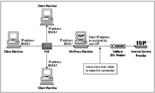
As you can see, only one computer—the WinProxy computer—has a modem. The other computers are connected to each other and to the WinProxy computer by a device called a hub (more on this later). The computer using the modem and receiving the WinProxy installation must be a Windows95/98 or Windows NT machine. Other computers on the local network can be any kind—including Macs, Unix boxes, and WfWG3.11—as long as they’re capable of “speaking” TCP/IP. Once you’ve drawn your network topography, including all components, make a list of everything you need.


Notes

1. Many cable modem providers insist on installing the cable modem card

themselves, and may insist upon using their own card. Before purchasing your

own cables and cards, check to see what the provider’s policy is.

2. If you have only two computers, it’s possible to save the expense of a

hub by connecting them back-to-back. To do so, run a cross-over cable directly

from one network card to the network card on the other machine. IP addressing

will still be done as described here

C. HARDWARE INSTALLATION/SETTING UP THE PEER-TOPEER

NETWORK


The best way to install an NIC is to simply follow the manufacturer’s directions. Win95/98 usually finds a new card when it starts up and then configures it for you. If it doesn’t, consult the directions that came with the card. Run a cable between each card and the hub (except for the external network card if you have a cable modem setup). Although you can probably get away with plugging/unplugging a cable from a card while the computer is running, it’s safer to do it when the computer is turned off. You can usually plug or unplug from the hub at any time.

You’ll need at least one protocol assigned to each card once it’s installed. Choose NetBEUI (NetBios Extended User Interface) at a minimum; you can have others as well. There isn’t any problem with having multiple protocols on your local network. You’ll need the TCP/IP protocol later in order to run WinProxy, but it’s not needed now when setting up a basic peer-to-peer network. Set up your basic network first, get it working, and we’ll add TCP/IP later on. During the card setup, you’ll be prompted for certain settings. If not already installed, be sure to add for each machine:

· Client for Microsoft Networks

· File and Printer Sharing

You can make changes to your settings at any time in the future. You must reboot the computer
for the changes to take effect.

D. INSPECTING AND CHANGING NETWORK SETTINGS

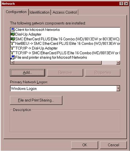
At this point, let’s double-check the computer network setup at Control Panel/Networks. In the window under the Configuration Tab, you’ll see a list of adapters and protocols. A typical setup is represented by a couple of small computer-shaped icons, one captioned Client for Microsoft Networks, and the other File and Printer Sharing. You’ll also see small green icons, similar in shape to a network card—one for each network card, and one for the Dial-Up Adapter (the Dial-Up Adapter counts as a network connection, with its own set of addresses and protocols). Finally, you’ll see a series of wire-and-node icons, each listing a different protocol-and-adapter combination, written in a form something like NetBEUI Æ NE2000 Compatible Card.


If you haven’t already added Client for Microsoft Networks, do so now:

· Highlight an adapter.

· Click through the path Add/Client/Microsoft/Client for Microsoft Networks.

To add a protocol capability to a network card:

· Highlight the network card.

· Click through the path Add/Protocol/Microsoft/Your Protocol. Click on the Identification Tab, where you’ll see three entry boxes titled:

Computer name: A name assigned by you to a computer (each computer on the network should have a unique name). Avoid punctuation marks. These names are frequently used in network configurations, and you’ll save confusion later by assigning distinctive names now. Old486 is a good name if you only have one 486 computer, but if you have several, assign them names like PapaBear, MamaBear, etc. NetBEUI uses this name to find things so it can perform its networking magic. You’ll sometimes see this computer name referred to as “the NetBios name.”

Workgroup Name: A group name you can assign to all the computers on your network (or you can use the default).

Computer Description: A caption that gives users on your local network information about an individual computer. An example: Maria’s Computer


Security Alert

The designated protocol will usually be assigned exactly as you’ve

requested. (In Windows 95 and 98, however, Microsoft assigns the NetBEUI

protocol to all network adapters when you assign it to any single network

adapter). If you don’t want that protocol in the other locations, highlight each one

you don’t want and click Remove.

A Final Word on Your LAN

Congratulations! You now possess a working local network. You can see the other computers, move files between them, and print documents. To prepare for WinProxy and the Internet, you’ll need to add the TCP/IP protocol to each of the computers on your local network. You’ll learn how to do so in the next chapter. Once that’s done, it’s on to WinProxy!

ADDING TCP/IP TO YOUR NETWORK

TCP/IP
Overview

The easiest way to install and configure WinProxy is to first add TCP/IP—the language spoken by WinProxy and the Internet—to your local network. This chapter covers the following topics:

1. Protocols and Addressing

2. Double-Checking Your Installed Network

3. Installing TCP protocol on your computers

4. Assigning IP addresses

5. Testing TCP/IP connectivity

A. FIRST THINGS FIRST: PROTOCOLS AND ADDRESSING Protocols. In networking terms the word “protocol” refers to the accepted standards or rules for the way data is transferred between computers and over the Internet. When everybody uses the same rules, it all works. There are many protocols in use. The three commonly used by local networks are NetBEUI, IPX/SPX, and TCP/IP.

NetBEUI is an acronym which stands for NetBios Extended User Interface. NetBEUI is a networking standard well suited for small networks and is easy to set up. It is also non-routable; since it uses computer names to find its way around, it can’t find distant computers.

IPX/SPX is Novell network’s version of IP addressing, used on Novell NetWare networks for both small and large systems. It works on Novell networks, but not between different types of networks (as TCP/IP will). TCP/IP, the language of the Internet, can be used on any size network. Data is sent over the network in chunks called packets. TCP (Transmission Control Protocol) is the protocol for packets of data sent over the wires. IP (Internet Protocol) is the addressing method used to get these packets to and from the right place. It is a routable protocol, designed to find distant computers. Some carefully-defined address groups are designated as intentionally non-routable; we’ll be using one of these to set up TCP/IP on your local network in the next chapter.

Network Addresses. These addresses may be assigned manually by the user, or automatically by another computer. They’re called static (i.e., fixed) assignments when assigned by the user, because they stay the same over time. When assigned automatically by computer, they’re known as dynamic (i.e., changing) assignments. If you connect via a dial-up connection, you’ll probably have a dynamic IP assignment to your Dial-Up Adapter. Your ISP assigns a different IP address to your Dial-Up Adapter each time you connect. If connecting with a cable modem, you’ll most likely have to make a static IP assignment for your Internet connection. Once this assignment is made, the IP address will not change. In addition, you’ll also have the choice of static or dynamic addresses on most of your networked computers. You can either set static IP addressing information yourself or have WinProxy make dynamic IP assignments for you. Addresses are not assigned to the computer itself, though people often speak that way as a convenient shorthand. The addresses are actually assigned to each network connection. The computer on which WinProxy will be installed, for instance, will have two network connections: an internal connection to the rest of your computers, and an external connection to your Internet Service Provider, or ISP.

In “Internet speak,” any machine with a network address is called a Host. For most simple TCP/IP systems, each host is a computer, and each computer is a host. The IP address is a 32-bit address, subdivided into four fields. Although it’s a binary number, it’s usually written in decimal form—222.5.83.47, for example. Each field can have a value from 0 through 255. However, since the end values are used for special purposes, the actual range available is from 1 to 254. What this boils down to for you, the user, is this: when entering an IP address, use only numbers between 1 and 254 in that last field.

Associated with the IP address is the subnet mask. This mask tells the computer which part of the address is unique to that machine, and which part is the general network address. Subnet masks allow you to accomplish many esoteric addressing capabilities; however, for most simple networks the subnet mask of 255.255.255.0 is the best and easiest choice. When you use this mask, the numbers in the final field of the IP address are unique to each computer, and the preceding three fields define the network address. To learn more about the intricacies of subnet masks. Some specific IP address ranges are reserved for special uses. We’ll discuss these later when setting up IP addressing on your local network. Network addresses reserved for testing or for local networks are 10.x.x.x, 90.x.x.x, 172.16-31.x.x and 192.168.x.x. These addresses all share a crucial distinction: routing computers on the Internet will not route these numbers. Since they are perfectly good numbers on a local network, but cannot be routed across the Internet, using them adds security to your local network.

Parts of a TCP packet are fields that specify the source and destination ports. These are 16-bit fields, and can thus specify more than 65 thousand ports. You’ll see many references to ports when interfacing your local net to the Internet. Ports 1 through 1024 are set aside for specific uses. Each Internet protocol has a standard port assigned to its use (e.g., Port 25 to send mail, Port 119 for news groups). In many cases, things can be easier to follow if you consider a port designation to be part of the address; some software even allows you to specify an IP address and port combination in the same statement.

B. DOUBLE-CHECKING YOUR INSTALLED NETWORK

Before going further, let’s double-check to be sure you have a basic network installed. At this point, your network should look like this:

· Your computers are connected via a working Ethernet network.

· One of the computers has an Internet connection, and is using Windows 95/98 or NT. That computer gets the WinProxy installation and will be known as the WinProxy computer.

· You already have some network protocols installed, including NetBEUI, and your computers already have NetBios names. The NetBios name of each computer can be found at Control Panel/Network/Identification/Computer Name. If your network doesn’t match these specifications, please bring it into line, using Chapter 3 to guide you, before attempting to install TCP Protocol and WinProxy. On the other hand, if you do have a basic network, read on!

C. INSTALLING TCP/IP PROTOCOL ON YOUR COMPUTERS

All communication between the client applications and WinProxy, and between WinProxy and the Internet, use TCP/IP protocols. Thus, the first thing you must do is add the TCP protocol and IP addresses to the network’s computers. As you proceed, pay attention to the dictates of the following three connection types:

1. The external WinProxy connection to the Internet. The type of IP address used—dynamic (commonly used for standard modems) or static (commonly used for cable modems)—is dictated by the ISP to which you connect and the type of service it provides.

2. The internal WinProxy connection. This connection must be a static IP assignment, and it must be assigned by you. Two reasons exist for a static assignment. First, some client applications must have a single, known address for the proxy server; second, the static assignment is used by WinProxy as a starting place for its DHCP assignments when providing tcp/ip assignments to your other computers.

3. The client computer network connections. These connections can be either dynamic or static. If they’re dynamic, WinProxy automatically makes all IP assignments and settings—the preferred method when using the WinProxy 3.0 Install Wizard. If they’re static, you must enter IP settings for each client computer. We recommend dynamic assignments for new users. Several protocols can co-exist on a local network, and you’ll usually need to have more than one. One protocol is sufficient on the connection to the Internet, and for security reasons you should have only TCP/IP. Let’s proceed. To install TCP.

1. On the machine receiving the WinProxy installation, click Control Panel/Network/Configuration. You’ll see a list of installed new components, and there should be listings for a Dial-Up adapter and a LAN adapter (exact wording varies). Look under LAN adapter to see if you have TCP installed—if it is, the listing will read something like TCP/IP ® LAN Adapter. Again, the exact wording varies.

2. If TCP/IP isn’t listed, click through this path: LAN Adapter/Add/Protocol/ Microsoft/TCPIP/
OK. That’s it! You’ll be prompted to restart, finishing the installation. Do so if you like, or you can wait until completing the next step before restarting.

3. Return to the initial screen. Look under Dial-Up Adapter to see if you have TCP/IP installed. If not, click through this path: DialUp Adapter/Add/ Protocol/Microsoft/TCP-IP/OK. When prompted to restart the computer, do so.

4. Add the TCP/IP protocol to each client machine (unless it’s already installed). The process is the same: in Control Panel/Networks look for a TCP/IP ® LAN Adapter line, adding the TCP/IP
protocol to the LAN adapter if it isn’t already installed.


For Client Machines Only

After completing Step 4, take a quick look at any dial-up adapters. If any are installed and have the
TCP protocol assigned, look under Properties to ensure that the dial-up adapter does not have the option
Assign a specific IP address selected. It should be set to Obtain an IP address automatically. This will

save you trouble down the road.

D. ASSIGNING IP ADDRESSES TO ALL NETWORK COMPUTERS

Each computer must be assigned a unique IP address. Strictly speaking, an IP address is assigned to each network connection, but it’s convenient to speak of a “machine address.” If you set your client computers to Obtain an IP address automatically (see the boxed note immediately above), WinProxy takes care of all of these settings for you. We recommend using the 90.0.0.x series of addresses on your local network. You’ll reap three major benefits by doing so:

· Your setup will match the numbers used for diagrams and instructions on the WinProxy website.

· You’ll find it much easier to follow explanations and trouble-shoot your network problems should the need arise.

· You’ll add to the security of your local computers by using this non-routing series on your local
network.

Now let’s proceed to assigning IP addresses.

1. First, let’s assign an IP address to the WinProxy machine. To do so, follow this path:

Control Panel/Network Configuration/TCP/IP/LANAdapter/Properties. Bring the IP Address Tab to the front. Click Specify an IP Address and enter an IP address and subnet mask. We recommend 90.0.0.1 and 255.255.255.0, as shown in the screen. You shouldn’t need to make any changes on other tabs for this basic installation.

2. Use the method shown above to install an IP address on each client machine. It’s easiest to use a sequential series such as 90.0.0.2, 90.0.0.3 and so on. Each computer gets a subnet mask of 255.255.255.0. Each IP address on your local network must be unique, and you can only vary the number in the final group—in other words, don’t change the 90.0.0 portion of the address.


3. If you’ll be using a dial-up connection to an Internet provider, the dial-up adapter does not get a specific IP assignment. Set it to Obtain an IP Address Automatically. The IP address for this connection will be dynamically assigned by the ISP each time you connect. These addresses come from a pool, and will probably (but not necessarily) be different each time you connect.

4. If, instead, you’ll be using a direct connection to your Internet provider (as many cable modems do), the network card connected to the modem should be assigned the IP address and subnet mask specified by your ISP for your individual Internet connection. Remember: you must have two network cards on this machine—one for the direct external connection to your provider and one for the internal connection to the rest of the computers on your local network.
The network card connecting to the rest of your local network retains the IP assignment it received in Step 1, above. At the conclusion of your installation, click through to WinProxy/Advanced Properties/General/ Multiple IP. While there, check to see that the IP number assigned to your Internet connection is defined as an external connection, and the IP number assigned to your local network is defined as an internal connection.

E. TESTING TCP/IP CONNECTIVITY


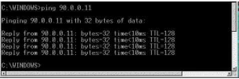
Now that you’ve added TCP/IP to all your computers, let’s run a test to determine if Network Neighborhood is up and running properly. If it is, you’ll know that the hub and cables are working correctly. We’ll use Ping for our test. It’s a simple tool included in Windows 95/98 and NT that allows easy checking of TCP/IP connectivity. First, open a DOS box (Start/Program/MS-DOS Prompt in Windows 95/98, and Start/Program/Command Prompt in Windows NT) and type the word ping. You’ll see a list of. commands and command syntax. If you’re on, say, client machine 90.0.0.2, you can check your connectivity to the WinProxy machine by typing in its IP address (90.0.0.1) after you type the word ping. If TCP/IP is properly set up on both machines you’ll get several lines that say Reply from 90.0.0.1…, as shown in the screen below. If you get no reply, something is wrong with the protocol installation of the IP address on one (or both) machines.

This series of three tests, run on each machine with a communications problem, will probably help isolate the problem:

1. Ping 127.0.0.1 to ensure that your tcp/ip software is working.

2. Ping yourself to ensure that the card is working.

3. Test to see that you can communicate with another machine.

· To run the first test (pinging the loopback address), type ping 127.0.0.1 at the DOS prompt. This verifies that the software TCP/IP stack on that machine is working and that the TCP protocol has been assigned (bound) to the card. The loopback address is specifically designated for such tests and doesn’t generate any actual network traffic. A failure at this point would implicate the software. If that’s the case, consider re-installing Winsock from your Windows CD-ROM, or download and install the latest Winsock from Microsoft.

· Now ping the IP address of the WinProxy computer, verifying that the card is working and IP addressing is correctly configured on that machine. If you discover a problem at this point, check to see that your network card is working properly. In Windows 95/98, go to Control Panel\System\Device Manager to see if there is a yellow exclamation point or question mark on your network card. If there is, click Drivers, and then choose View Resources to determine if Windows reports a conflict—e.g., an interrupt conflict. If so, you may be able to resolve the conflict by assigning an unused interrupt. If not, try reinstalling the card.

· Ping the IP address of another machine on your network. To work properly, the configuration must be correct on both machines. A problem at this stage usually indicates an IP addressing error. You’ve probably violated one of the basic IP rules, perhaps assigning the same number to two different machines, assigning a number outside the allowed range, or simply mis-typing an address. Check and double-check the assigned addresses. If you get a response such as request timed out, it means that ping did not reach (or return from) the other machine. Look for misconfigured IP addresses or unplugged hubs. If your response is something like destination unreachable, then ping didn’t know how to follow through on your request. You might get this response if, for example, you pinged an address with a different set of network fields. Look for misnamed nets or misconfigured subnet masks.


USER’S CHECKPOINT: If everything works except the last test (pinging another computer) an
old proxy installation may be interfering. Proxy software that requires installation of software
components on client machines as well as on the proxy server can cause tcp/ip communication
problems. This software must be removed from each machine for proper tcp/ip communication.

If there seems to be a problem with a network card, go to Control Panel/ System/Device Manager/View Devices by Type. Look under Network Adapters. If you see a yellow exclamation point or question mark over the adapter, the system is having a problem with that adapter. Use the Win95/98 wizards to help track down problems. If you upgraded from Windows 95 to Windows 98, your network card drivers are probably out of date. Download new drivers made specifically for Windows 98 from the manufacturer’s web site.


Dial UP Technology

| 0 responce(s) |
|

Dial-up Technology

Dialup is simply the application of the Public Switched Telephone Network (PSTN) to carry data on behalf of the end user. It involves a customer premises equipment (CPE) device sending the telephone switch a phone number to direct a connection to. The AS3600, AS5200, AS5300, and AS5800 are all examples of routers that have the capability to run a PRI along with banks of digital modems. The AS2511, on the other hand, is an example of a router that communicates with external modems. Since the time of Internetworking Technologies Handbook, 2nd edition, the carrier market has continued to grow, and there have been demands for higher modem densities. The answer to this need was a higher degree of interoperation with the telco equipment and the refinement of the digital modem: a modem capable of direct digital access to the PSTN. This has allowed the development of faster CPE modems that take advantage of the clarity of signal that the digital modems enjoy. The fact that the digital modems connecting into the PSTN through a PRI or a BRI can transmit data at more than 53 K using the V.90 communication standard attests to the success of the idea.

A Short Dialup Technology Background

Dialup technology traces its origins back to the days of the telegraph. Simple signals being sent across an extended circuit were created manually by tapping contacts together to turn the circuit either on or off. In an effort to improve the service, Alexander Graham Bell invented the telephone in 1875 and changed communication forever. Having the capability to send a voice across the line made the technology more accessible and attractive to consumers. By 1915, the Bell system stretched from New York to San Francisco. Demand for the service drove technological innovations, which led to the first transatlantic phone service in 1927 via radio signal. Other innovations along the way included. microwave stations that started connecting American cities in 1948, integrated digital networks to improve the quality of service, and communication satellites, which went into service in 1962 with the launch of Telstar 1. By 1970, more than 90 percent of American homes had telephone service. In 1979 the modulator-demodulator (modem) was introduced, and dialup networking was born. The early modems were slower and subject to proprietary communication schemes. Early uses of modems were for intermittent point-to-point WAN connections. Often, the call would come into a regular phone at a data center. An operator would hear modem tones and place the handset onto a special cradle that was the modem. In the late 1980s, the ITU-T began setting up V-series recommendations to standardize communications between both data communications equipment (DCE) and data terminal equipment (DTE). Early standards included these:

• V.8—Standardized the method that modems use to initially determine the V-series modulation at which they will communicate. Note that this standard applies only to the communication session between the two DCE devices. This was later updated with V.8bis, which also specified some of the communication standards between the DTE devices going over the DCE’s connection.
• V.21, V.23, V.27ter, V.29—Defined 300, 600/1200, 2400/4800, and 9600 baud communications, respectively.
• V.25, V.25bis, V.25ter—Served as a series of standards for automated dialing, answering, and control. Modems increased greatly in sophistication in the late 1980s. This was due in part to the breakup of the Bell system in 1984. With the client premises equipment in the hands of free enterprise, competition spurred on the development of speedier connections. More recent standards include these:
• V.32bis, V.34, V.90—Standardized 14400, 33600, and up to 56000 baud communication speeds.
• V.110—Allowed an asynchronous DTE device to use an ISDN DCE (terminal adapter). The first access servers were the AS2509 and the AS2511. The AS2509 could support 8 incoming connections using external modems, while the AS2511 could support 16. The AS5200 was introduced with 2 PRIs and could support 48 users using digital modems—this represented a major leap forward in technology. Modem densities have increased steadily, with the AS5300 supporting four and then eight PRIs. The AS5800 was later introduced to fill the needs of carrier class installations needing to handle dozens of incoming T1s and hundreds of user connections A couple of outdated technologies bear mentioning in a historical discussion of dialer technology. 56
Kflex is an older (pre-V.90) 56 K modem standard that was proposed by Rockwell. Cisco supports version 1.1 of the 56 Kflex standard on its internal modems, but it recommends migrating the CPE modems to V.90 as soon as possible. Another outdated technology is the AS5100. The AS5100 was a joint venture between Cisco and a modem manufacturer. The AS5100 was created as a way to increase modem density through the use of quad modem cards. It involved a group of AS2511s built as cards that were inserted into a backplane shared by quad modem cards, and a dual T1 card. Today dialup is still used as an economical alternative (depending on the connection requirements) to dedicated connectivity. It has important uses as backup connectivity, in case the primary lines go down. Dialup also offers the flexibility to create dynamic connections as needed.

Dialup Connectivity Technology

This section provides information from various dialup options. Also included are advanced options for dialup connectivity and various dialup methods.

Plain Old Telephone Service

The regular phone lines used in voice calls are referred to as Plain old telephone service (POTS). They are ubiquitous, familiar, and easy to obtain; local calls are normally free of charge. This is the kind of service that the phone network was built on. Sounds carried over this service are sampled at a rate of 8000 times per second (using 8 bits per sample) in their conversion to digital signals so that sound can be carried on a 64 kbps channel at acceptable levels.The encoding and decoding of voice is done by a piece of telco gear called a CODEC. The CODEC was needed to allow backward-compatibility with the old analog phones that were already in widespread use when the digital network was introduced. Thus, most phones found in the home are simple analog devices. Dialup connectivity across POTS lines has historically been limited to about 33,600 bps via modem—often referred to as V.34 speeds. Recent improvements have increased the speed at which data can be sent from a digital source to a modem on a POTS line, but using POTS lines on both ends of the connection still results in V.34 connectivity in both directions.

Basic Rate Interface

Intended for home use, this application of ISDN uses the same copper as a POTS line, but it offers direct digital connectivity to the telephone network. A special piece of equipment known as a terminal adapter is required (although, depending on the country, it may be integrated into the router or DCE device). Always make sure to check—the plug used to connect to the wall socket looks the same whether it’s the S/T or U demarcation point. Normally, a Basic rate interface (BRI) interface has two B (bearer) channels to carry data, and one D (delta) channel to carry control and signaling information. Local telephone carriers may have different plans to suit local needs. Each B channel is a 64 K line. The individual 64 K channels of the telephone network are commonly referred to as digital service 0 (DS0). This is a common denominator regardless of the types of services offered, as will be shown later in this chapter. The BRI interface is a dedicated connection to the switch and will remain up even if no calls are placed. The T1/E1 line is designed for use in businesses. T1 boasts 24 TDM channels run across a cable with 2 copper pairs. E1 offers 32 channels, although 1 is dedicated to frame synchronization. As is the case with the BRI, the T1/E1 connection goes directly into the telco switch. The connection is dedicated, so like a BRI, the T1/E1 remains connected and communicating to the switch all the time—even if there are no active calls. Each of the channels in the T1/E1 is just a B channel, which is to say that it’s a 64-K DS0. The T1/E1 is also referred to as digital service 1 (DS1). The North American T1 uses frames to define the timing between individual channels. For T1s, each frame has 24 9-bit channels (8 bits of data, 1 bit for framing). That adds up to 193 bits per frame. So, at
8000 of those per second, the T1 is carrying 1.544 Mbps between the switch and the customer premises equipment (CPE). The E1 similarly uses frames for timing, but the E1 uses 32 8-bit channels for a 256-bit frame. Again at the 8000 Hz rate, the channel yields 2.048 Mbps of traffic between the switch and the CPE. Most of the world uses the E1. Depending on the region, various line code and framing schemes will have to be used for the CPE and the switch to understand each other. For example, in North America, the encoding scheme most often seen is called binary 8 zero substitution (B8ZS), and the most common framing done is extended super frame (ESF). The telco through which the T1/E1 service is purchased must indicate which line code and framing should be used. For dialup purposes, there are two types of T1/E1: Primary Rate Interface (PRI) and channel associated signaling (CAS). PRI and CAS T1/E1s are normally seen in central locations that receive calls from remote sites or customers.

Primary Rate Interface

T1 Primary rate interface (PRI) service offers 23 B channels at 64 kbps at the cost of one D-channel (the 24th channel) for call signaling. Using NFAS to allow multiple PRIs to use a single D channel can minimize this disadvantage. E1 PRI service allows 30 channels, but it uses the 16th channel for ISDN signaling. The PRI service is an ISDN connection. It allows either voice-grade (modem) or true ISDN calls to be made and received through the T1/E1. This is the type of service most often seen in access servers because it fosters higher connection speeds.

Channel Associated Signaling

T1 Channel associated signaling (CAS) lines have 24 56K channels—part of each channel is borrowed for call signaling. This type of service is also called robbed-bit signaling. The E1 CAS still uses only the 16th channel for call signaling, but it uses the R2 international standard for analog call signals. CAS is not an ISDN interface; it allows only analog calls to come into the access server. This is often done to allow an access server to work with a channel bank, and this scenario is seen more commonly in South America, Europe, and Asia,sends a call into a channel that isn’t expecting it, the switch will get back a message indicating that the channel isn’t available. An access server must maintain state information on its lines and be prepared to coordinate inward and outward calls with the switch.

Modems

From a terminology standpoint, a modem is considered data communication equipment (DCE), and the device using the modem is called data terminal equipment (DTE). As indicated earlier, modems must adhere to a number of communication standards to work with other modems: Bell103, Bell212A, V.21, V.22, V.22bis, V.23, V.32, V.32bis, V.FC, and V.34, to name a few. These standards reflect a dual analog conversion model,Notice that the signal goes through only one analog conversion. Because the conversion is done on the client’s side, traffic generated by the client modem is limited to V.34 speeds. The traffic coming from the access server is not subject to the noise problems that an analog conversion would introduce, so it can be sent at much higher speeds. Thus, the client can receive data at v.90 speeds but can send data at only V.34 speeds.

PPP -

PPP bears mentioning because it is so vital to the operation of dialup technologies. Until PPP came along in 1989 (RFC 1134—currently up to RFC 1661), dialup protocols were specific to the protocol being used. To use multiple protocols, it was necessary to encapsulate any other protocols within packets of whatever protocol the dialup link was running. Many of the proprietary link methods (such as SLIP) didn’t even have the capability to negotiate addressing. Fortunately, PPP does this and many more things with flexibility and extensibility. PPP connection establishment happens in three phases: Link Control Protocol (LCP), authentication, and Network Control Protocol (NCP).

LCP-

LCP is the lowest layer of PPP. Because PPP does not follow a client/server model, both ends of the point-to-point connection must agree on the negotiated protocols. When negotiation begins, each of the peers wanting to establish a PPP connection must send a configure request (CONFREQ). Included in the CONFREQ are any options that are not the link default. These often include maximum receive unit, async control character map, authentication protocol, and the magic number. At this stage, the peers negotiate their authentication method and indicate whether they will support PPP multilink. In the general flow of LCP negotiations, there are three possible responses to any CONFREQ:

1. A configure-acknowledge (CONFACK) must be issued if the peer recognizes the options and agrees to the values seen in the CONFREQ.
2. A configure-reject (CONFREJ) must be sent if any of the options in the CONFREQ are not recognized (such as some vendor-specific options) or if the values for any of the options have been explicitly disallowed in the configuration of the peer.
3. A configure-negative-acknowledge (CONFNAK) must be sent if all the options in the CONFREQ are recognized, but the values are not acceptable to the peer. The two peers continue to exchange CONFREQs, CONFREJs, and CONFNAKs until each sends a CONFACK, until the dial connection is broken, or until one or both of the peers indicates that the negotiation cannot be completed.

Authentication

Authentication is an optional phase, but it is highly recommended on all dial connections. In some
instances, it is a requirement for proper operation—dialer profiles, being a case in point. The two principal types of authentication in PPP are the Password Authentication Protocol (PAP) and the Challenge Handshake Authentication Protocol (CHAP), defined by RFC 1334 and updated by RFC 1994. When discussing authentication, it is helpful to use the terms requester and authenticator to distinguish the roles played by the devices at either end of the connection, although either peer can act in either role. Requester describes the device that requests network access and supplies authentication information; the authenticator verifies the validity of the authentication information and either allows or disallows the connection. It is common for both peers to act in both roles when a DDR connection is being made between routers. PAP is fairly simple. After successful completion of the LCP negotiation, the requester repeatedly sends its username/password combination across the link until the authenticator responds with an acknowledgment or until the link is broken. The authenticator may disconnect the link if it determines that the username/password combination is not valid. CHAP is somewhat more complicated. The authenticator sends a challenge to the requester, which then responds with a value. This value is calculated by using a “one-way hash” function to hash the challenge and the CHAP password together. The resulting value is sent to the authenticator along with the requester’s CHAP host name (which may be different from its actual host name) in a response message. The authenticator reads the host name in the response message, looks up the expected password for that host name, and then calculates the value that it expects the requester to send in its response by performing the same hash function the requester performed. If the resulting values match, the authentication is successful. Failure should lead to a disconnection. By RFC standards, the authenticator can request another authentication at any time during the connection.

NCP-

NCP negotiation is conducted in much the same manner as LCP negotiation with CONFREQs, CONFREJs, CONFNAKs, and CONFACKs. However, in this phase of negotiation, the elements being negotiated have to do with higher-layer protocols—IP, IPX, bridging, CDP, and so on. One or more of these protocols may be negotiated. Refer to the following RFCs for more detail on their associated protocols:

• RFC 1332 “IP Control Protocol”
• RFC 1552 “IPX Control Protocol”
• RFC 1378 “AppleTalk Control Protocol”
• RFC 1638 “Bridging Control Protocol”
• RFC 1762 “DECnet Control Protocol”
• RFC 1763 “VINES Control Protocol”

A Couple of Advanced Considerations

The Multilink Point-to-Point Protocol (MLP, RFC 1990) feature provides a load-balanced method for splitting and recombining packets to a single end system across a logical pipe (also called a bundle) formed by multiple links. Multilink PPP provides bandwidth on demand and reduces transmission latency across WAN connections. At the same time, it provides multivendor interoperability, packet fragmentation with proper sequencing, and load calculation on both inbound and outbound traffic. The Cisco implementation of multilink PPP supports the fragmentation and packet sequencing specifications in RFC1717. Multilink PPP works over the following interface types (single or multiple):

• Asynchronous serial interfaces
• BRIs
• PRIs

Multichassis multilink PPP (MMP), on the other hand, provides the additional capability for links to terminate at multiple routers with different remote addresses. MMP can also handle both analog and digital traffic. This functionality is intended for situations in which there is a large pool of dial-in users, and a single access server cannot provide enough dial-in ports. MMP allows companies to provide a single dialup number to their users and to apply the same solution to analog and digital calls. This feature allows Internet service providers, for example, to allocate a single ISDN rotary number to several ISDN PRIs and not have to worry about whether a user’s second link is on the same router. MMP does not require reconfiguration of telephone company switches.

AAA

Another technology that should be mentioned because of its importance is Authentication, Authorization, and Accounting (AAA). The protocols used in AAA can be either TACACS or RADIUS. These two protocols were developed in support of a centralized method to keep track of users and accesses made on a network. AAA is employed by setting up a server (or group of servers) to centrally administer the user database. Information such as the user’s password, what address should be assigned to the user, and what protocols the user is allowed to run can be controlled and monitored from a single. workstation. AAA also has powerful auditing capabilities that can be used to follow administratively important trends such as connection speeds and disconnect reasons. Any medium or large dialup installation should be using AAA, and it’s not a bad idea for small shops, either.

Dialup Methods

Most routers support automated methods for dynamic links to be connected when traffic that needs to get to the other end arrives. Cisco’s implementation is called dial-on-demand routing (DDR). It provides WAN connectivity on an economical, as-needed basis, either as a primary link or as backup for a nondial serial link. At its heart, DDR is just an extension of routing. Interesting packets are routed to a dialer interface that triggers a dial attempt. Each of the concept’s dialer interface and interesting traffic bear explanation.

What’s a Dialer?

The term dialer has a few meanings, depending on the specifics of the configuration, but in general, it refers to the interface where the routing is actually happening. This is the interface that knows the address and phone number where the traffic is supposed to go. When looking at the routing table, the dialer interface should be the interface referenced for the next hop to reach the network on the other side. The dialer interface does not have to be the physical interface that is doing the dialing, but it can be made so by placing the configuration command dialer in-band in a physical interface. Thereafter, the interface becomes a dialer. For example, an async interface is not a dialer by default, but placing the configuration command dialer in-band in the async interface causes dialer behavior on that interface. For example, calls received by that async interface after applying the command will have an idle timeout applied to the connection from then on. An example of a physical interface that is also a dialer by default would be the BRI interface. Beyond making physical interfaces into dialers, there are interfaces called dialer interfaces. These are logical interfaces that call upon real interfaces to place calls. The advantage of using a dialer interface is flexibility. A group of potential DDR links can share a handful of BRI interfaces. Dialer interface configuration comes in two flavors: dialer map-based (sometimes referred to as legacy DDR) and dialer profiles. Which method you use depends on the circumstances under which you need dial connectivity. Dialer map-based DDR was first introduced in IOS Version 9.0; dialer profiles were introduced in IOS Version 11.2.

Interesting Traffic

The term interesting is used to describe packets or traffic that will either trigger a dial attempt or, if a dial link is already active, reset the idle timer on the dialer interface. For a packet to be considered interesting, it must have these characteristics:

• The packet must meet the “permit” criteria defined by an access list.
• The access list must be referenced by the dialer–list, or the packet must be of a protocol that is
universally permitted by the dialer–list.
• The dialer-list must be associated with a dialer interface by use of a dialer group.

Packets are never automatically considered to be interesting (by default). Interesting packet definitions must be explicitly declared in a router or access server configuration.

Benefits and Drawbacks

The benefits of dialup are flexibility and cost savings. First, let’s look at why flexibility is important. Intermittent connectivity is most often needed in mobile situations. A mobile workforce needs to be capable of connecting from wherever they are. Phone lines are normally available from wherever business is transacted, so a modem connection is the only reasonable choice for mobile users. In long-distance situations, a user often dials into a local ISP and uses an IPSec-encrypted tunnel going back to a home gateway system that allows access to the rest of the corporate network. In this example, the phone call itself costs nothing, and an account with the local ISP could be significantly less expensive than the long-distance charges that would otherwise be incurred. As another example, a BRI attached at a central office located in an area that offers inexpensive rates on ISDN could have database servers configured to call out to other sites and exchange data periodically. Each site needs only one BRI line, which is significantly less expensive than dedicated links to each of the remote locations. Finally, in the case of a backup link, the savings are seen when the primary link goes down but business continues, albeit slower than normal. Cost savings is a two-edged sword where dialup is concerned, however. The downside of a dialup line is that connection costs for a heavily used line are higher than the price of dedicated connectivity. Going over long distance raises the price even higher. There’s also speed to consider. Dialup connectivity has a strong high-end bandwidth, particularly with the capability to tie channels together using PPP multilink, but dedicated connectivity through a serial port can outperform dialup connections. Another consideration is security. Certainly, any PPP connection should be authenticated, but this presents anyone with the dialup number an opportunity to break into the system. A significant part of any dialup system’s configuration concerns the capability to keep out unwanted guests. The good news is that it can be done, and AAA goes a long way toward dealing with this problem. However, it is a disadvantage to have potential intruders coming in through dialup lines.

Telecommunications Systems

| 0 responce(s) | Sunday, May 17, 2009
|

Telecommunications Systems

So as we proceed through this material, try not to get frustrated with the constant mix of services, technological discussions, and costing issues. From time to time, we may also introduce some extra technical notes that are for the more technically astute but can be ignored by the novice trying to progress through the industry. As you read about a topic, do so with a focus on systems, rather than individual technologies. We have tried to make these somewhat stand-alone chapters, yet we have also tied them together in bundles of three or four chapters to formulate a final telecommunications system. Do what you must to understand the information, but do not force it as you read. The pieces will all come together throughout the groupings of topics.

What Constitutes a Telecommunications System

A network is a series of interconnections that form a cohesive and ubiquitous connectivity arrangement when all tied together. That sounds rather vague, so let’s look at the components of what constitutes the telecommunications network. The telecommunications network referred to here is the one that was built around voice communications but has been undergoing a metamorphosis for the past two decades. The convergence of voice and data is nothing new; we have been trying to run data over a voice network since the 1970s. However, to run data over the voice network, we had to make the data look like voice. This caused significant problems for the data because the voice network was noisy and error-prone. Reliability was a dream and integrity was unattainable, no matter what the price.

Generally speaking, a network is a series of interconnection points. The telephone companies over the years have been developing the connections throughout the world so that a level of cost-effective services can be achieved and their return on investment (ROI) can be met. As a matter of due course, whenever a customer wants a particular form of service, the traditional carriers offer two answers:

1. It cannot be done technically.
2. The tariff will not allow us to do that!

Regardless what the question happened to be, the telephone carriers were constantly the delay and the limiting factor in meeting the needs and demands for data and voice communications.
In order to facilitate our interconnections, the telephone companies installed wires to the customer’s door. The wiring was selected as the most economical to satisfy the need and the ROI equation. Consequently, the telephone companies installed the least expensive wiring possible. Because they were primarily satisfying the demand for voice communications, they installed a thin wire (26-gauge) to most customers whose locations were within a mile or two from the central office. At the demarcation point, they installed the least expensive termination device (RJ-11), satisfying the standard two-wire unshielded twisted pair communications infrastructure. The position of the demarcation point depended on the legal issues involved. In the early days of the telephone network, the telephone companies owned everything, so they ran the wires to an interface point and then connected their telephone equipment to the wires at the customer’s end. The point here is that the telephone sets were essentially commodity-priced items requiring little special effect or treatment.

When the data communications industry began during the late 1950s, the telephone companies began to charge an inordinate amount of money to accommodate this different service. Functionally, they were in the voice business and not the data business. As a matter of fact, to this day, most telephone companies do not know how to spell the word data ! They profess that they understand this technology, but when faced with tough decisions or generic questions, few of their people can even talk about the services. How sad, they will be left behind if they do not change quickly. New regulations in the U.S., in effect since the divestiture agreement, changed this demarcation point to the entrance of the customer’s building. From there, the customer hooked up whatever equipment was desired. Few people remember that in early 1980, a 2400-bps modem cost $10,000. The items that customers purchase from a myriad of other sources include all the pieces we see during the convergence process. In the rest of the world today, where full divestiture or privatization has not yet taken place, the telephone companies (or PTTs) still own the equipment. Other areas of the world have a hybrid system under which customers might or might not own their equipment. The combinations of this arrangement are almost limitless, depending on the degree of privatization and deregulation. However, the one characteristic that is common in most of the world to date is that the local provider owns the wires from the outside world to the entrance of the customer’s building. This local loop is now under constant attack from the wireless providers offering satellite service, local multipoint distribution services (LMDS), and multi-channel multi-point distribution services (MMDS). Moreover, the CATV companies have installed coaxial cable or fiber, if new wiring has been installed, and they offer the interconnection to business and residential consumers alike. The CLECs have also emerged as formidable foes to the local providers. They are installing fiber to many corporate clients (or buildings) with less expense and long-term write-off issues. The CLECs are literally walking away from the telephone companies and the local loop. Add the xDSL family of products to this equation and the telephone companies are running out of options. The telephone companies today have approximately 15,000 xDSL connections across the U.S., whereas the CLECs have over 200,000. Moreover, the cable TV companies have close to 800,000 cable modems installed for high-speed Internet access. This is where the CATV companies see the convergence taking place. CLECs are also seeing the convergence in the local loop, and with xDSL in their potpourri of offerings, they are actually nudging the local telephone
companies aside.

A Topology of Connections Is Used

In the local loop, the topological layout of the wires has traditionally been a single-wire pair or multiple pairs of wires strung to the customer’s location. Just how many pairs of wires are needed for the connection of a single line set to a telecommunications system and network? The answer (one pair) is obvious. However, other types of services, such as digital circuits and connections, require two pairs. The use of a single or dual pair of wires has been the norm. More recently, the local providers have been installing a fourpair (eight wires) connection to the customer location. The end user is now using separate voice lines, separate fax lines, and separate data communications hookups. Each of these requires a two-wire interface from the LEC. However, if a CATV provider has the technology installed, they can get a single coax to satisfy the voice, fax, data, and highspeed Internet access on a single interface, proving the convergence is rapidly occurring at the local loop. It is far less expensive to install a coax running all services (TV, voice, and data) than multiple pairs of wire, so the topology is a dedicated local connection of one or more pairs from the telephone provider to the customer location or a shared coax from the CATV supplier. This is called a star and/or shared star-bus configuration . The telephone company connection to the customer originates from a centralized point called a central office (CO). The provider at this point might be using a different topology. Either a star configuration to a hierarchy of other locations in the network layout or a ring can be used. The ring is becoming a far more prevalent method of connection for the local Telcos. Although we might also show the ring as a triangle, it is still a functional and logical ring. These star/ring or star/bus combinations constitute the bulk of the networking topologies today. Remember one fundamental fact: the telephone network was designed to carry analog electrical signals across a pair of wires to recreate a voice conversation at both ends. This network has been built to carry voice and does a reasonable job of doing so. Only recently have we been transmitting other forms of communication, such as facsimile, data, and video.

The telephone switch (such as DMS-100 or #5ESS) makes routing decisions based on some parameter, such as the digits dialed by the customer. These decisions are made very quickly and a cross-connection is made in logic. This means that the switch sets up a logical connection to another set of wires. Throughout this network, more or fewer connections are installed, depending on the anticipated calling patterns of the user population. Sometimes there are many connections among many offices. At other times, it can be simple with single connections. The telephone companies have begun to see a shift in their traffic over the past few years. More data traffic is being generated across the networks than ever before. As a matter of fact, 1996 marked the first year that as much data was carried on the network as voice. Since that time, data has continued its escalated growth pattern, whereas voice has been stable.


The Local Loop

Our interface to the telephone company network is the single-line telephone line, which has been installed for decades and is written off after 30 or 40 years. Each subscriber or customer is delivered at least one pair of wires per telephone line. There are exceptions to this rule, such as when the telephone company might have multiple users sharing a single pair of wires. If the number of users demanding telephone service exceeds the number of pairs available, a Telco might offer the service on a party-line or shared set of wires. It is in this outside plant, from the CO to the customer location, that 90 percent of all problems occur. This is not to imply that the Telco is doing a lousy job of delivering service to the customer. In the analog dial-up telephone network, each pair of the local loop is designed to carry a single telephone call to service voice conversations. This is a proven technology that works for the most part and continues to get better as the technologies advance. What has just been described is the connection at the local portion of the network. From there, the local connectivity must be extended out to other locations in and around a metropolitan area or across the country. The connections to other types of offices are then required.


The Telecommunications Network

Prior to 1984, most of the network was owned by AT&T through its local Bell operating telephone companies. A layered hierarchy of office connections was designed around a five-level architecture. Each of these layers was designed around the concept of call completion. The offices were connected together with wires of various types called trunks . These trunks can be twisted pairs of wire, coaxial cables (like the CATV wire), radio (such as microwave), or fiber optics. As the convergence of voice and data networks continues, we see a revisitation to the older technologies as well as the new ones. Fiber is still the preferred medium from a carrier’s perspective. However, microwave radio is making a comeback in our telecommunications systems, linking door-to-door private line services. Carrying voice, data, video, and high-speed Internet access is a natural for a microwave system. Lightbased systems, however, are limited in their use by telephone companies. It has been user demand that has brought infrared light and now SONET-based infrared systems in place. Recently, the introduction of an unguided light introduced by Lucent Technologies operates at speeds up to 2.4 Gbps with a promised speed of up to 10 Gbps by end of 2000. This offers the connectivity to almost anyone who can afford the system, because the right of way is no longer an issue.


The Network Hierarchy (Post-1984)

After 1984, ownership of the network took a dramatic turn. AT&T separated itself from the Bell Operating Companies (BOCs), opening the door for more competition and new ventures. Equal access became a reality and users were no longer frustrated in their attempts to open their telecommunications networks to competition.


The Public-Switched Network

The U.S. public-switched network is the largest and the best in the world. Over the years, the network has penetrated to even the most remote locations around the country. The primary call-carrying capacity in the U.S. is done through the public-switched network. Because this is the environment AT&T and the BOCs built, we still refer to it as the Bell System. However, as we’ve already seen, significant changes have taken place to change that environment. The public network enables access to the end office, connects through the long-distance network, and delivers to the end. This makes the cycle complete. Many companies use the switched network exclusively, while others have created variations depending on need, finances, and size. The network is dynamic enough, however, to pass the call along longer routes through the hierarchy to complete the call in the first attempt wherever possible.


The North American Numbering Plan

The network-numbering plan was designed to enable a quick and discreet connection to any telephone in the country. The North American Numbering Plan , as it is called, works on a series of 10 numbers. As progress occurs, the use of Local Number Portability (LNP) and Intelligent Networks (IN) enables the competitors to break in and offer new services to the consumer. Note that there have been some changes in this numbering plan. When it originally was formulated, the telephone numbers were divided into three sets of sequences. The area codes were set to designate high-volume usage and enabled some number recognition tied to a state boundary. With the convergence in full swing, the numbering plan became a bottleneck. Now with the use of LNP, the Numbering Plan will completely become obsolete as we know it. No longer will we recognize the number by an area code and correlate it to a specific geographic area. LNP will make the number a fully portable entity. Moreover, 10-digit dialing in the age of convergence becomes the norm because of the multitude of area codes that will reside in a state.


Private Networks

Many companies created or built their own private networks in the past. These networks are usually cost-justified or based on the availability of lines, facilities, and special needs. Often these networks employ a mix of technologies, such as private microwaves, satellite communications, fiber optics, and infrared transmission. The convergence of the networks has further been deployed because of the mix of services that the telephone companies did not service well. Many companies with private networks have been subjected to criticisms because the networks were misunderstood. Often the networks were based on voice savings and could not be justified. Now that the telecommunications networks and systems are merging, the demand for higher-speed and more availability is driving either a private network or a hybrid.


Hybrid Networks

Some companies have to decide whether to use a private- or public-switched network for their voice, data, video, and Internet needs. Therefore, these organizations use a mix of services based on both private and public networks. The high-end usage is connected via private facilities creating a Virtual Private Network (VPN), while the lower-volume locations utilize the switched network. Installing private-line facilities comes from the integration of voice, data, video, graphics, and facsimile transmissions. Now VPNs are used on the Internet to guarantee speed, throughput, quality of service, and reliability. This new wave of VPN takes up where the voice VPNs left off. Only by combining these services across a common circuitry will many organizations realize a savings.


Equipment
Equipment in the telephony and telecommunications business is highly varied and complex. The mix of goods and services is as large as the human imagination, yet the standard types are the ones that constitute the ends on the network. The convergence and computerization of our equipment over the years has led to significant variations. The devices that hook up to the network are covered in various other chapters, but here is a summary of certain connections and their functions in the network:

• The Private branch exchange ( PBX)
• The modem (data communications device)
• The multiplexer (enables more users on a single line)
• Automatic call distributor (ACD)
• Voice mail system (VMS)
• Automated attendant (AA)
• Radio systems
• Cellular telephones
• Facsimile machines
• CATV connections
• Web-enabled call centers
• Integrated voice recognition and response systems

This is a sampling of the types of equipment and services you will encounter in dealing with Telecommunications Systems and convergence in this industry.


Enter your email address:

Delivered by FeedBurner